Let’s assume the sign is perpendicular to the road. Because the sign is 6 m above the road, the starting entrance angle at 500 m (1640 ft) is about 0.6°. The observation angle can be measured by drawing a line from the left headlight to the sign and back to the driver’s eye. In our case, the observation angle starts at 0.06°. In the lab, the rotation angle is typically changed by rotating the sign. On the road, it can be changed by rotating the retroreflector or rotating the position of the driver in respect to the light source. Because the driver does not sit perfectly above the left headlight, our rotation angle starts at about 22° (clockwise from the driver’s perspective).
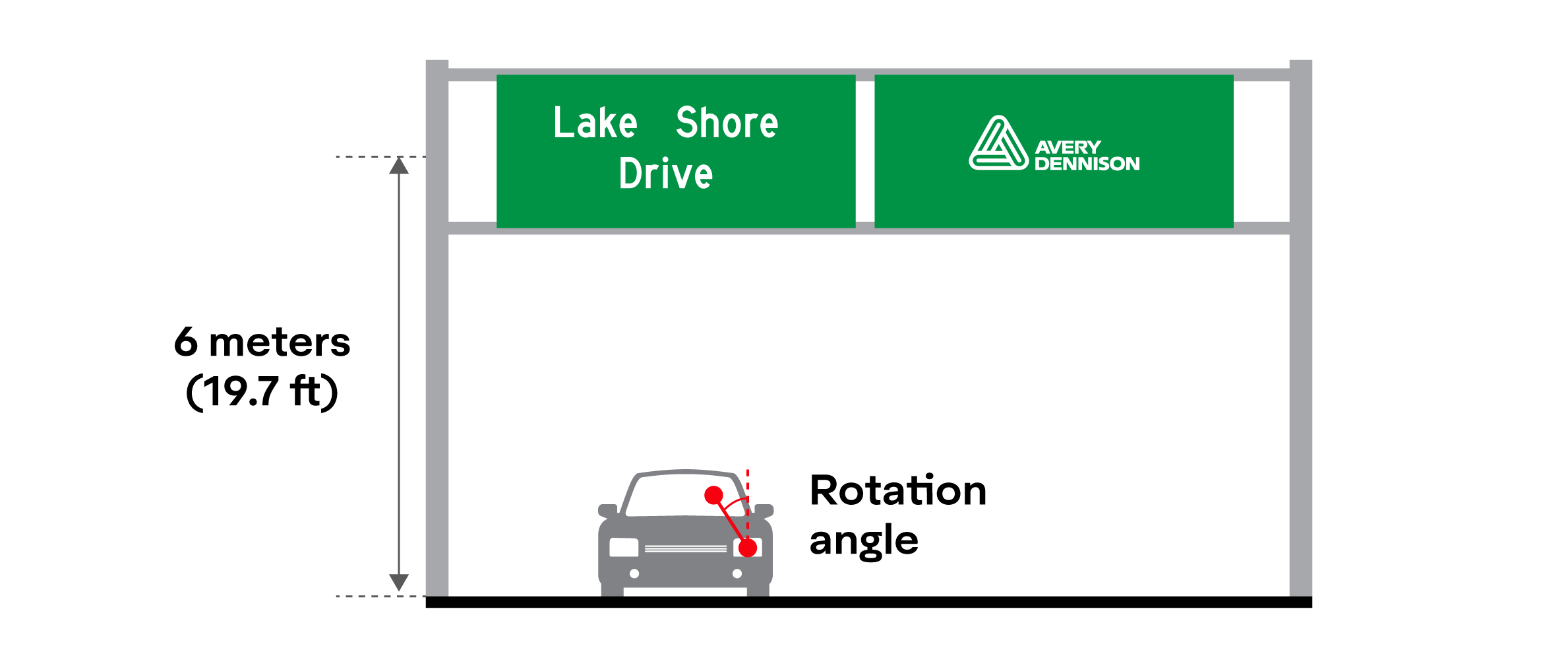
As our sedan approaches the guide sign, our entrance angle, observation angle, and rotation angle will change.
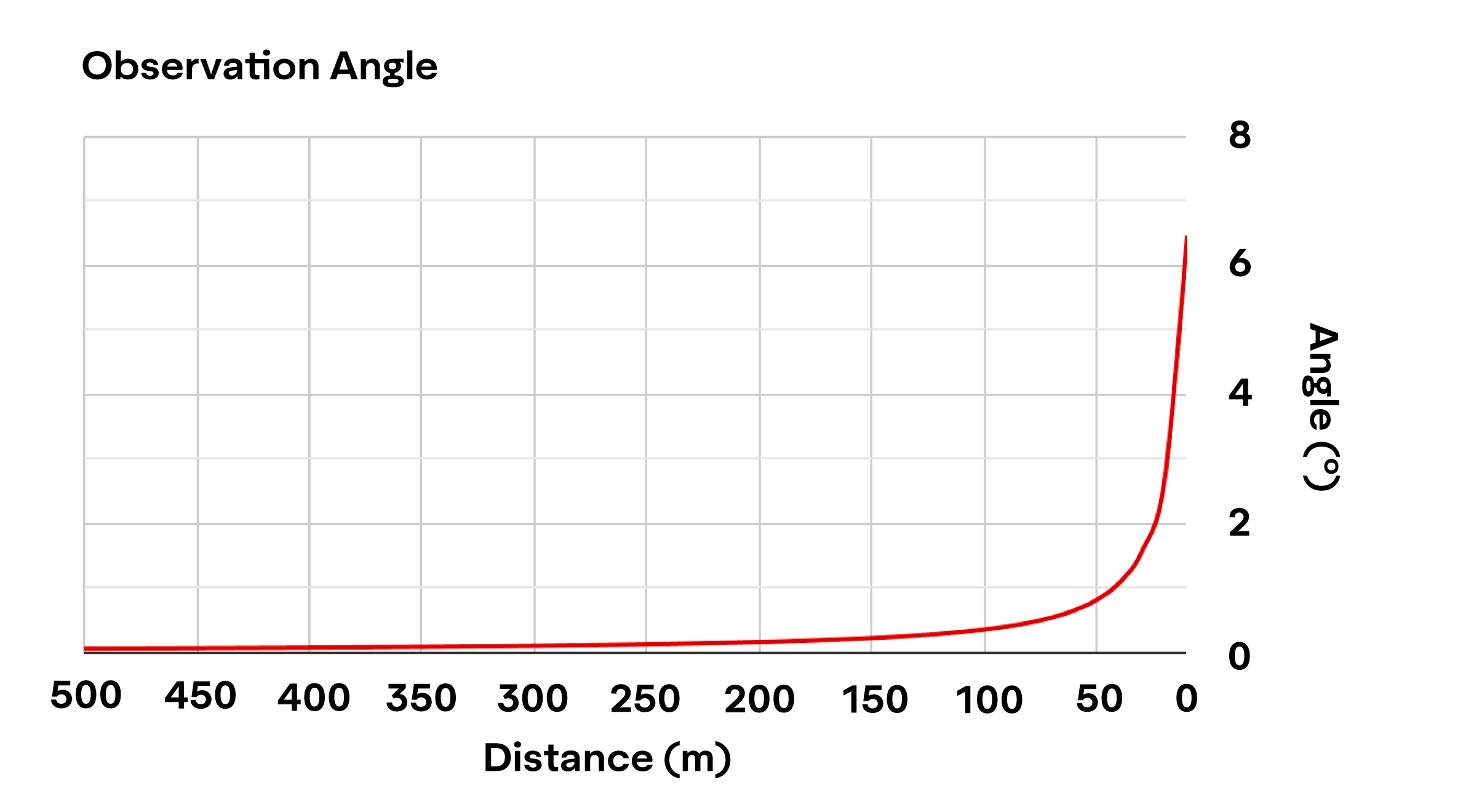
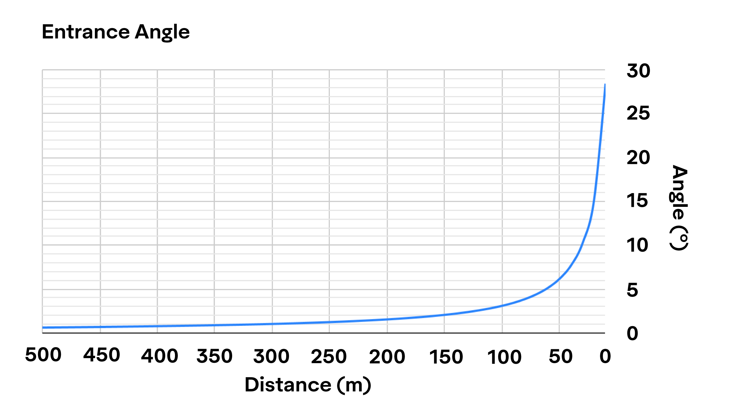
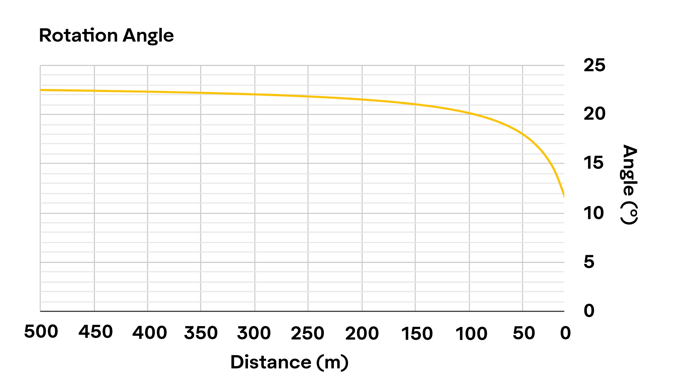
There are several important items to note: the entrance angle of 4° discussed in the spec and lab scenario of Chapter 6 occurs somewhere in between 70 to 80 m (230 ft to 262 ft). The observation angle of 0.2° occurs at about 170 m (558 ft). In other words, the combination of 4° entrance angle, 0.2° observation angle, and 0° rotation angle do not occur at the same time on the road. An entrance angle of 4°, and an observation angle of 0.5°, which occurs at about 70 m to 80 m (230 ft to 262 ft), may be the closest geometry found within specs for a sedan, but even then, our rotation angle is about 19°. Additionally, this close combination only occurs for an instant as the sedan drives towards the sign.
Our scenario only gets more complicated when we consider different vehicles, headlights, sign locations, wider roads, and/or curves on the road. There is also the fact that we are measuring a retroreflector’s ability to send light back in a particular direction whereas, all else being equal, a driver cares about luminance, i.e.: intensity of light coming from a surface per unit area. To calculate luminance, in our simplified scenario, we would also need to consider the second headlight, understand the light distribution from both headlights, and take hundreds of retroreflectivity measurements to account for the geometry changes as the sedan approaches the sign. Then there are driver, lighting conditions, and sign size differences to consider.
Over the years, there has been a lot of human factors research on what drivers need in terms of luminance, color, size, and more, but we will cover some of those in future chapters. For now, suffice it to say that road scenarios are much more complicated than specifications can cover. Additionally, specifications were initially written for beaded products where retroreflectivity is more predictable due to the spherical nature of glass beads. As a result, the geometry combinations, such as an entrance angle of 4° and 30°, were chosen as quality control measures to test the extreme extent of what may occur on the road. From there, it was assumed that retroreflectivity would change gradually as a vehicle approaches a sign. Over time, systems, equipment, and even conventions were set up to test using these geometries.