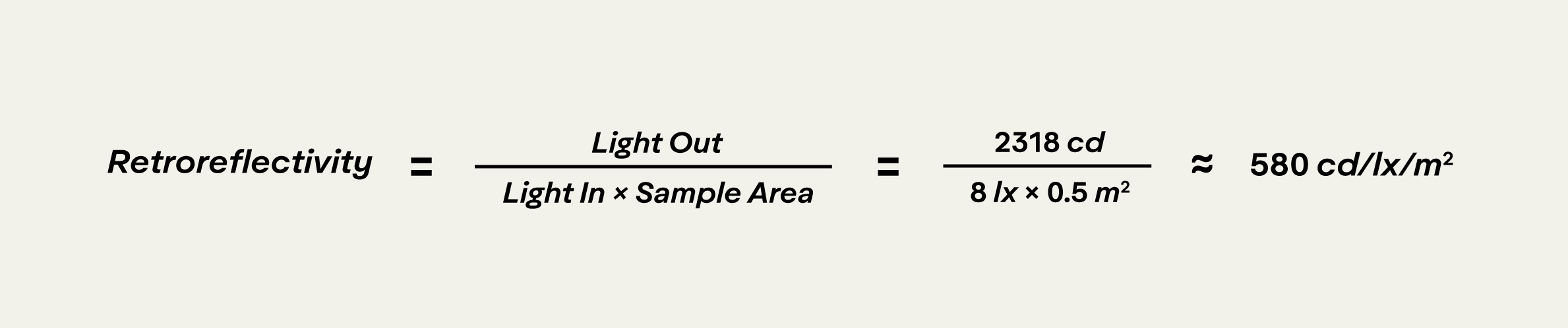
Let’s assume we have a fixed light source pointed towards a 0.5 m2 sample. It provides the sample with an illuminance of about 8 lx (lumens/m2) - this is our “light in”. The retroreflector, depending on its size (m2) and orientation will collect a portion of the “light in”. Our sample has an entrance angle component of -4° in accordance with the spec (which is the same as an entrance angle of 4° since β can only be positive.) This means that our sample is facing slightly away from the light source; it is also only 0.5 m2. As a result, it will only collect about 4 lumens (lm) of the light available to it.
If the retroreflector is able to return 50% of the energy it collects, a total of about 2 lumens will be sent back out. Of course, if our sample was getting more or less light than the scenario depicted, its brightness would change. The reality is that the “brightness” of a retroreflector, i.e. what the driver sees, is contingent on many factors, including headlight intensity, headlight direction, sign location, and more. Since we cannot test every scenario, we need to instead measure how efficiently the retroreflector sends the available light back in a particular direction.
We use a receiver sensor with a 1 inch (0.0254 m) diameter aperture to measure a spot within the cone of retroreflectivity at a distance of 15 m. Let’s assume that our sensor, positioned at an observation angle of 0.2°, and a rotation angle of 0°, collects 0.00522 lm of light. This tells us how much light the sensor is receiving, but 15 m has no real significance other than being a practical distance for lab measurements. The amount of light collected by the sensor would change depending on its size and distance from the retroreflector. The closer and larger the detector, the more light (lumens) it would collect because it would occupy a larger portion of the cone of retroreflection.
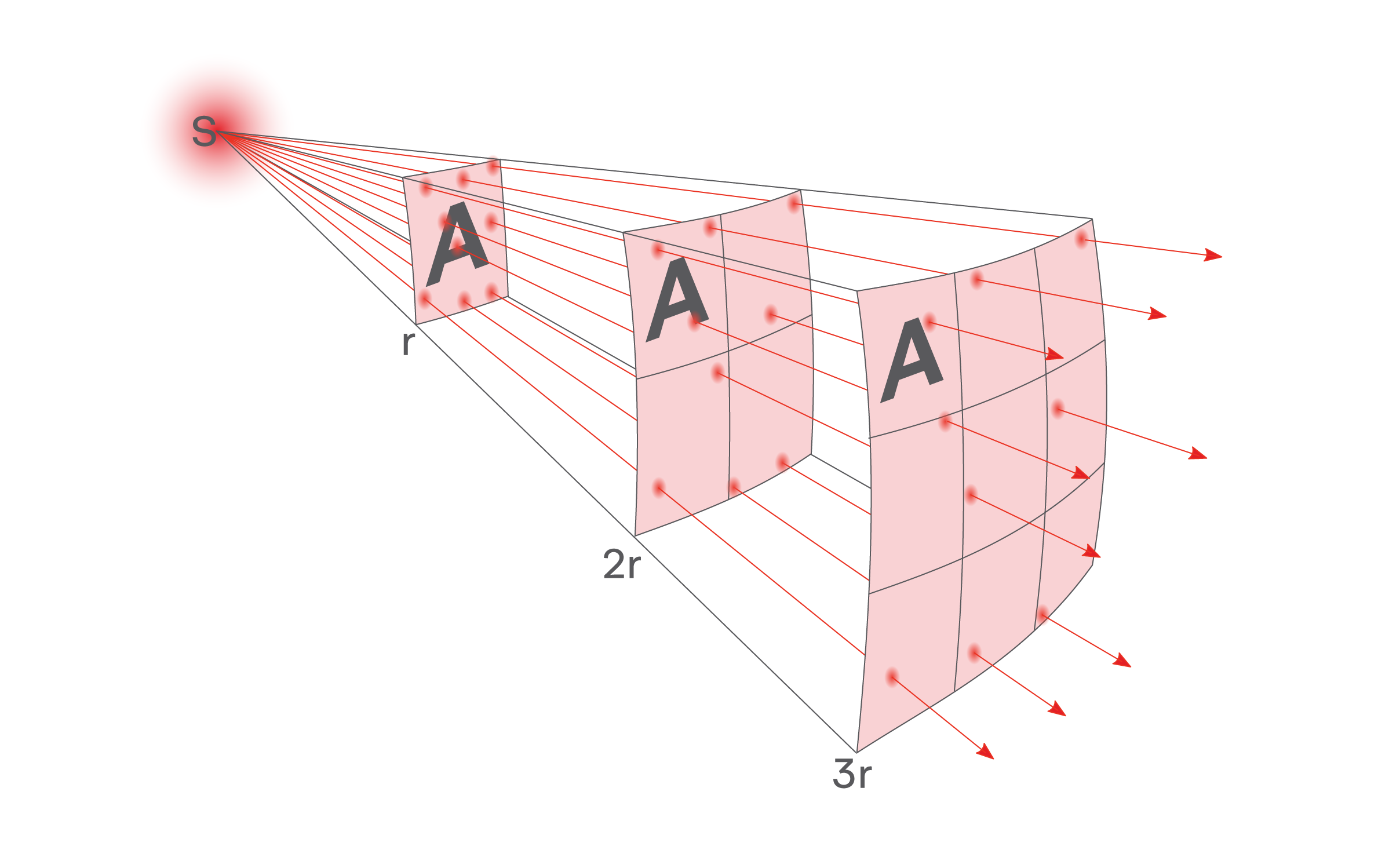
As a result, it is more helpful to know the intensity of light heading towards the detector (candelas or lumens/steradian) which does not depend on distance or detector size. The area of our sensor and its distance from the retroreflector form a “solid angle” (Ω) within the cone of retroreflectivity, which we can use to factor out the area of our sensor and its distance from our sample. In other words, we can use the solid angle to figure out light intensity (lumens/steradian), which is our “light out”.
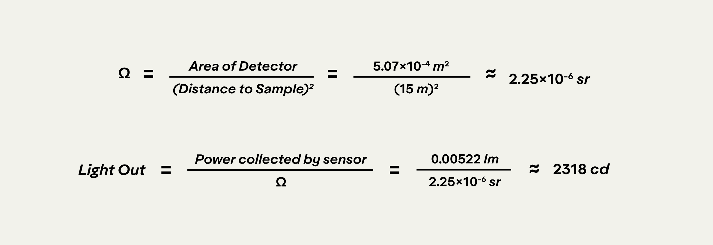
We now know that our light out in the direction of our sensor is about 2318 cd, and our light in is 8 lx. Since the amount of light collected and returned also depends on the size of the retroreflector, the last step is to divide by the sample area (in this case 0.5 m2) to determine our retroreflectivity measurement.