Chapter Select

Learn Sheeting: Chapter 5—Measuring Retroreflectivity (Angles)

Chapter 4 offered an overview of how retroreflection is measured. We alluded to the fact that retroreflectivity is measured by checking a specific spot within the larger cone of retroreflectivity. To control how light enters a retroreflector, and identify the position of the spot within the returning light that is being measured we use four angles: observation angle, two different entrance angle components, and rotation angle.

Observation Angle

The line that’s created from the center of the light source to the center of the retroreflector is called the illumination axis. Similarly, the line between the center of the retroreflector and the center of the receiver is called the observation axis. The angle that’s created between the illumination axis and observation axis is called the observation angle (α). Observation angles are never negative numbers, and almost always less than 10°. More often, they are no more than 2°. In simple terms, this measurement indicates how far from the center of the cone of retroreflection a measurement should be taken.


Entrance Angle

A perpendicular line going out from the center of the retroreflector is called the retroreflector axis. The angle between the illumination axis and the retroreflector axis is known as the entrance angle (β). Simply put, this is the angle at which the light enters the retroreflector, where head-on equals 0°. As such, the entrance angle can only be positive. However, we often use two entrance angle components (β1 and β2) which can be positive or negative. By convention, the entrance angle can be positive or negative depending on which way the retroreflector is tilted. The “up and down” entrance angle component is annotated as β1 while the “side to side” entrance angle component is annotated as β2. Entrance angles are usually no larger than 90°. Most specifications do not go beyond 30°.


Rotation Angle

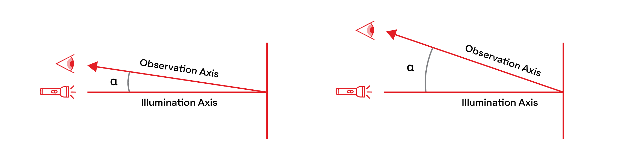
It would be easier to explain how rotation angle changes than to define it. Rotation angle (ε) can be decreased or increased by rotating the sample clockwise or counter-clockwise, or by rotating the receiver around the light source. Rotation angle can range from 0° to 360°, starting at the 12 o’clock position and rotating clockwise. While observation angle dictates how far from the center of the cone of retroreflectivity our receiver should be, rotation angle dictates its rotation.


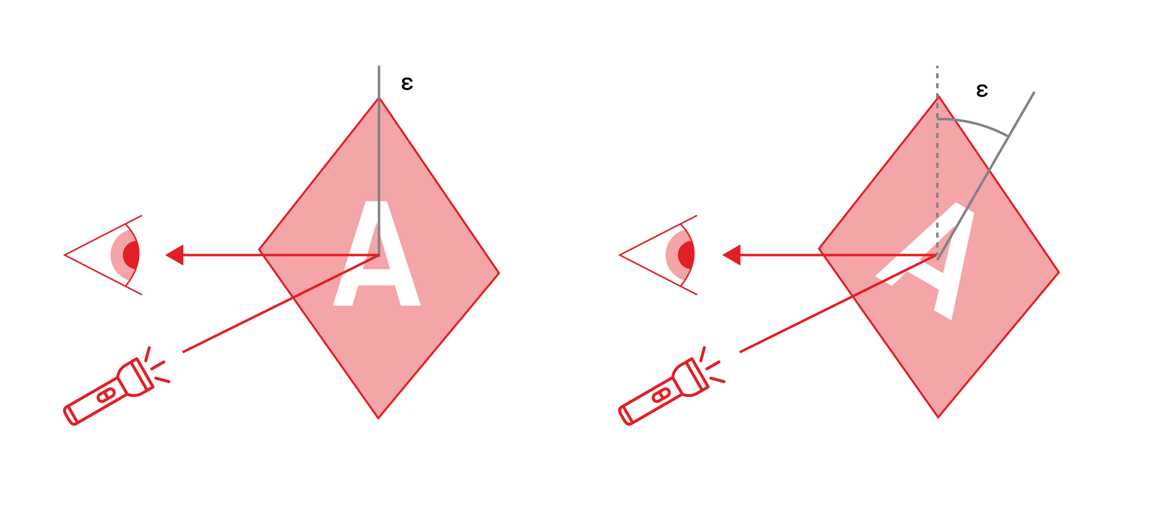
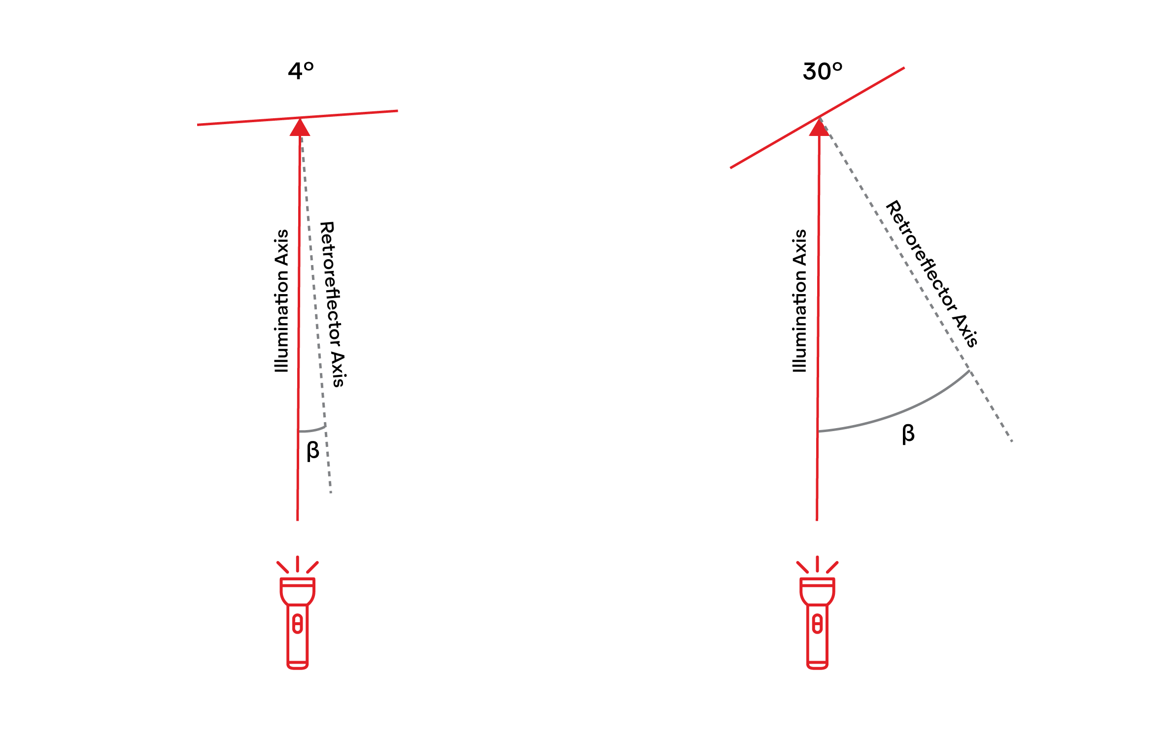
It should be noted that in the lab (ignoring portable equipment), the light source almost always has a fixed position while the receiver moves up and down to control the observation angle, and the sample is tilted from side to side or up and down to change the entrance angle. Because the light source and receiver are fixed on the same vertical plane (up and down with respect to each other), the rotation angle is controlled by rotating the sample. Ultimately, what we are trying to control is the relative position of the retroreflective elements to our light source and receiver.

Previous Chapter

Learn Sheeting: Chapter 4—Measuring Retroreflectivity

Learn More arrow_forward

Next Chapter

Learn Sheeting: Chapter 6—Sign Specification

Learn More arrow_forward

Be the First to Learn More

SUBSCRIBE